Purpose
Designing a pull up bar is a great engineering project to apply the subjects of statics and mechanics of solids to a manageable real-world project and to learn about DIY hardware. If you’re not an engineering student, don’t worry, you just need to know simple math for this article (you’ll learn a lot along the way). 9/10 times it’s easier and cheaper to just buy a pull up bar (if you factor in the time-cost it takes you to build and design something), but if you can’t find what you’re looking for, engineering a product is your only choice.
Requirements
Before buying anything, doing any math, 3D modeling, or building anything, we need to define what we want our pull up bar to do. For the sake of this tutorial we want our bar to:
- be free standing (i.e. not wall or door mounted)
- strong enough for a 175 lb male + 50 lbs of additional weight
- be at least as tall as a door-way pull up bar (~6 ft)
- moderately portable: simple to put together/take apart for moving/traveling
- multi-functional (can hang laundry on it or hang objects to be spray painted)
- wide enough for gymnastic rings
- Between 46-50 inches [^fn1]
- Between 1-2 inches in diameter [^fn1]
- Max load of 400-550 lbs [^fn1]
- be shiny
Math
DISCLAIMER: I hate doing math for any project. I’d rather just start building something. However, after many failed projects, I’ve learned that the tradeoff between skimping on the math is spending a lot of time and money experimenting and building multiple prototype. Sometimes it’s worth experimenting more if the time it would take you to solve a problem analytically/computationally is too long, but just some food for thought.
Here’s the Google Sheets where all the math and parts are listed out: https://docs.google.com/spreadsheets/d/1Fs1gMRC-DVFi9r2xmKxOBZuFfL0cmqJVwHxTdkonaYQ/edit?usp=sharing. Copy it to your drive and fill it out after reading the article. Regardless of what we design, we’ve got to figure out if our materials will break under load.
Stress/Yielding
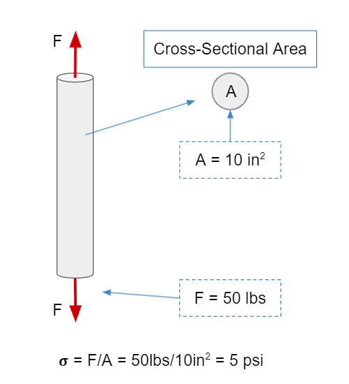
A material permanently deforms when it experiences stress greater than it’s yield stress (σ > σyield). The equation for stress is simply the force an object experiences divided by its cross-sectional area:
\[\sigma = {F \over A}\]If the stress is parallel to the cross-sectional area that’s tensile/compressive stress (depending on the direction), and if it’s perpendicular to the area, then it’s shear stress. In English, we can see what that means in the diagrams below where our force is in lb-force, our area is in in2, and our stress is in psi.
- Tensile Stress
![]()
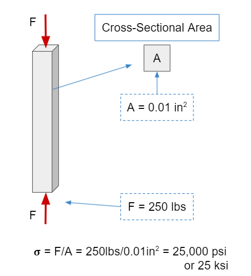
- Compressive Stress
![]()
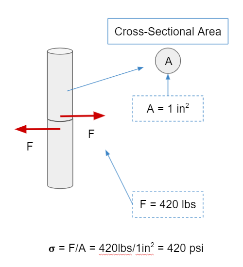
- Shear Stress
![]()
We can find the tensile stress of things like 1020 cold-rolled steel (a common type of steel) and different types of wood by Googling on a site like azom or matweb:
1020 cold-rolled steel: σyield = 50800 psi [^fn2]
aluminum 6061: σyield = 40,000 psi [^fn3]
When calculating the bending stress on the bar, it’s important that we don’t go over the yield strength σyield. Note: yield strength is typically much lower than the stress at which the bar breaks/snaps in half: σultimate. We typically use yield strength because we don’t want a deformed pull up bar.
Bending Stress
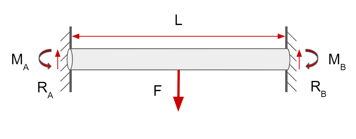
The bending stress on the pull up bar is the stress experienced on the bar when you hang on it, either with one or two hands. As seen in the diagram below, it’s greatest at the ends of the bar, and the bar is in compression at the top and tension at the bottom.
To calculate the bending stress, we use this equation: \(\sigma = {My \over I}\) where y is the distance from the center of the bar, M is the moment (we’ll get to that in a second), and I is a geometric property of the cross-sectional area called the second moment of area or moment of inertia. A list of formulas for moment of inertia can be found here for common shapes. Since a pull-up bar is usually a pipe, the formula for that moment of inertia is given by the formula below (where OD and ID refer to outer and inner diameter respectively): \(I_{pipe} = \frac{\pi}{64}(OD^4-ID^4)\)
Because we’re trying to figure out the maximum bending stress, y is equal to the OD of the pipe, where the stress is greatest. To find the biggest moment M on the bar, we need to create a bending moment diagram. Now, it’s not entirely important that you know how to create a bending moment diagram from scratch (if you want to know how to, watch this video: link) because there’s only 3 scenarios we care about and all of them can be found in textbooks (their derivation is intuitively difficult due to being statically determinate, so I’m just going to do them myself and provide formulas for the MAXIMUM moment for each).
We can also substitute these equations into the equation for bending stress to calculate the maximum force F these three configurations can handle (isn’t math fun?!).
- Hanging in the Middle
![]()
The equation for the maximum moment is given by the textbook Deflection of Beams Dr. T.H.G. Megson, in Structural and Stress Analysis (Fourth Edition), 2019 link:
\[M = {FL \over 8}\] \[F_{max}={8\sigma I \over yL}\]- Equidistant Hanging
![]()
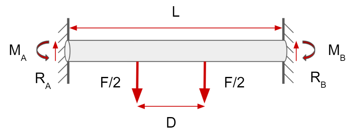
Using the solution we got from “hanging in the middle,” we can say that the maximum moment is given by:
\[M=\max \left \{M_a={F(L^2-D^2) \over 8L},M_a={F(L-D) \over 4} \right\}\] \[F_{max}=min\left ( \frac{8L\sigma I}{y(L^2-D^2)},\frac{8L\sigma I}{y(L-D)(D-L)} \right )\]- Grabbing one-handed
![]()
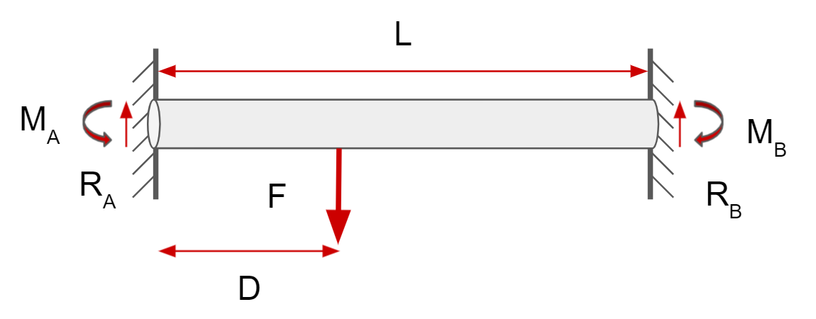
The equation for the maximum moment is given by the textbook Deflection of Beams Dr. T.H.G. Megson, in Structural and Stress Analysis (Fourth Edition), 2019 link:
\[M= {F(D)(L-D)^2 \over L^2}\] \[F_{max}=\frac{\sigma IL^2}{yD(L-D)^2}\]where D < (L-D).
Now we can plug these into our happy excel sheet and find the maximum force the pipe can hold (once we have a specific pipe in mind). It should also be noted that this analysis is incomplete without considering the total stress at a given point due to the reaction forces + the bending stress at the two ends A & B, as well as conducting an FEA simulation to confirm my results. But hey, I said I’m an engineer, not a thorough engineer (we’ll get to it if we have extra time).
Buckling
The critical load due to buckling is the maximum weight the columns holding up the pullup bar can support. You’d think it would just be related to the compressive strength of the bar, but because no force is perfectly compressive along the axis of the column (to see what I mean, watch this video), the formulas we use is given below:
\[F=nEI(\frac{\pi}{L})^2\]where F is called the critical load and n is found in this diagram:
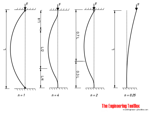 source: engineering toolbox
- column pivoted in both ends : n = 1 (can rotate but can’t move vertically or horizontally)
- both ends fixed : n = 4 (can’t rotate or move vertically or horizontally)
- one end fixed, the other end rounded : n = 2
- one end fixed, one end free : n = 0.25 (For our analysis, we’ll select this one. Our pull-up bar columns won’t be completely free floating, but this is a good, conservative selection)
and E is a value called the Young’s Modulus (another good video on the topic). The Young’s modulus or the “Modulus of Elasticity” is unique for each material and a measure of a how stiff a material is (the higher the number, the stiffer the material is).
- 1020 cold-rolled steel: E = 27000 ksi (remember 1 ksi = 1000 psi) [^fn2]
- aluminum 6061: E = 10,000 ksi (from this, we can see that aluminum is almost 3 times less stiff than steel, which is why it wouldn’t make for a great pullup bar.) [^fn3]
The Young’s modulus is often used in this equation:
\[E=\frac{\sigma}{\epsilon}\]where ϵ is called the strain in a material and itself is explained by this formula:
\[\epsilon=\frac{x}{L}\]where x is the change in length or deformation of a material and L is just the length of the material…that’s a lot of equations, but I’ll throw one more at you. In order to figure out if buckling is the dominant mode of failure for a beam (instead of compression or just compression), we need to calculate the slenderness ratio = L/r, where r is called the “radius of gyration” and given by the equation below: [^fn4]
\[r=(\frac{I}{A})^{1/2}\]That’s actually it for the math…for now :)
Concepts
Before 3D modeling, I ALWAYS recommend drawing up a few concepts to prevent yourself from wasting a bunch of time. I made these by sketching in OneNote. Your drawing skills might be better or worse, and you might not be familiar enough with hardware you can get from amazon/homedepot/local hardware stores/etc, but definitely start with a sketch as a jumping off point.
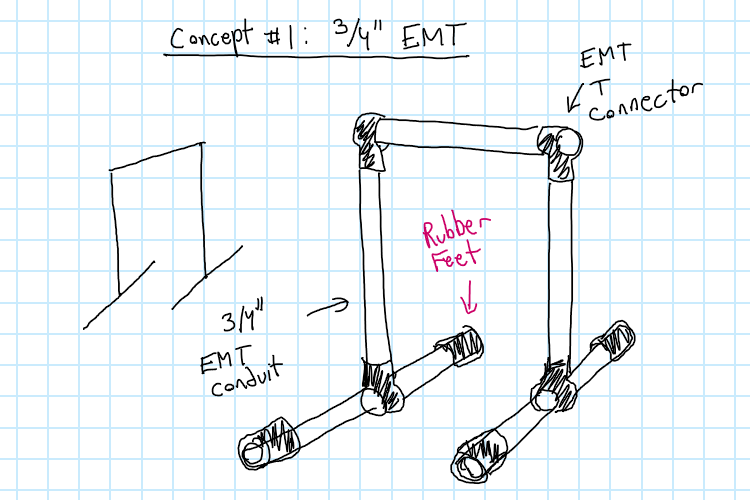 Concept #1
Pros
- shiny
- uses simple connectors that I already own
- easy to assemble and disassemble
- Could theoretically adjust the height if needed Cons
- Probably more expensive than anything that uses wood
- restricted to 3/4” EMT conduit if using makerpipe T connectors meaning it’s going to be somewhat weak
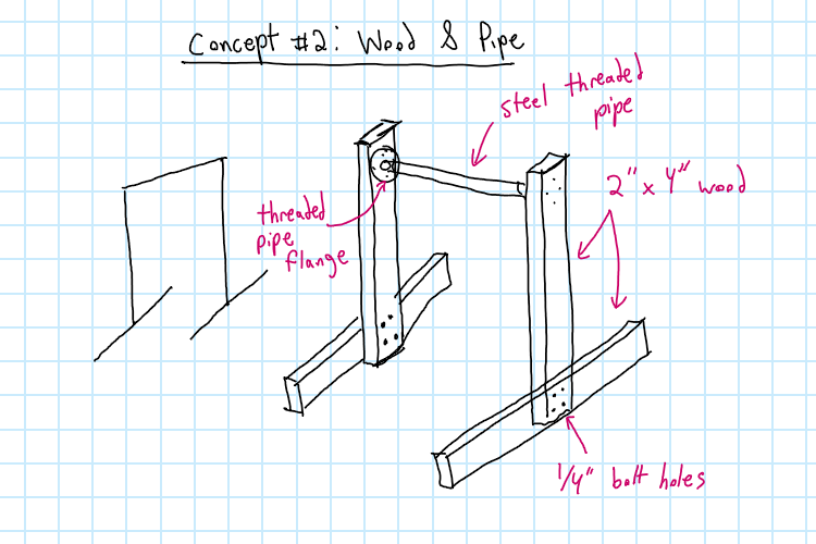 Concept #2
Pros
- uses affordable 2x4 lumber
- wood easy to cut and drill
- threaded flanges and pipe are much stronger Cons
- Going to be a bit bulkier than using steel
- Needs polyurethane or shellac or to be painted
- Going to be a bit harder to take apart and transport
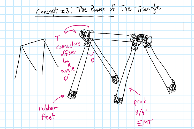 Concept #3
Pros
- same pros as concept 1
- should be stronger than concept 1 because the supports would be under bending and not buckling Cons
- might be annoying aligning all the angles when building
- more expensive than concept 1 as will require more pipe
- Takes up more room
Parts List
The parts list I use can be found in the excel sheet: https://docs.google.com/spreadsheets/d/1Fs1gMRC-DVFi9r2xmKxOBZuFfL0cmqJVwHxTdkonaYQ/edit?usp=sharing. My process is to simultaneously 3D model and create a parts list. Often times you can find 3D models of commonly available things on
3D Model
Build
- Take your 3 3/4” EMT conduit pipes and with a tape measurer and a marker mark out:
- 75”
- 75”
- 50 & 3/4”
- Put a little cutting oil on the pipe cutter
- Cut the pipes (using gloves to avoid callouses)
- Use a reamer to ream out the 50 & 3/4” pipe
- Using a rubber mallet very gently and carefully hammer in the pipe 60” reinforcing pipe to the 50 & 3/4” segment
- On the remaining two pieces from the first 2 cuts, measure and mark out the center of the pipes with a marker
- Add the T connector to the centers of these pipes and attach the 75” pipes
- On the top of the 75” pipes add a T connector and place the 50 & 3/4” pipe through them
- Cut up the rubber tubing in 8 segments
- 4 x 6in segments
- 4 x 12 in segments
- Attach the rubber like so
- (Optional) use pipe clamps to prevent the inner pipe from moving